Diagram A Circuit That Employs The 2s-complement Negation Tr
[diagram] 2 s complement logic diagram Solved: a) design a four-bit 2's complement circuit with a control Solved design a circuit that computes the twos complement of
Solved Here is a two's complement representation of an | Chegg.com
Figure 1 from design and implementation of high performance two’s Solved schematic below represents a given circuit with two [diagram] 2 s complement logic diagram
2's complement circuit. compared to a conventional adder 2's complement
[solved]: problem 1: question consider the two circuit diaSolved march 23rd: (lecture #20) use two's complement wat s Binary subtraction with two's complementFra221b6574: บทสรุปการเรียน week2.
Figure 4 from an approach for realization of 2's complement adderSolved here is a two's complement representation of an Solved circuit iiSolved 2) two circuit diagrams are given below. a given.

Answered: consider the two circuit diagrams…
Solved design the following circuit for 2s complementSolved combinational circuit for twos complementer Understanding two's complementVerilog 2 complemento de complemento / surtración.
Solved 1- draw the logic circuit diagram that implement the[diagram] 2 s complement circuit diagram Question #01 a. explain if the circuit in figure 2 isSolved circuit 2 figure 4. circuit 2 schematic circuit 2.

[diagram] 2 s complement logic diagram
Solved circuit below is a two's complement generator using jTwo’s complement Design a combinational circuit that produce 2’s complement of a 4-bitComplement twos binary.
Complement adder subtractor gate realization reversible dkgComplement binary two bit number subtraction twos integers figure represented negative Solved consider the two circuit diagrams below. these twoFull adder and subtractor circuit diagram.
Consider the two circuit diagram below
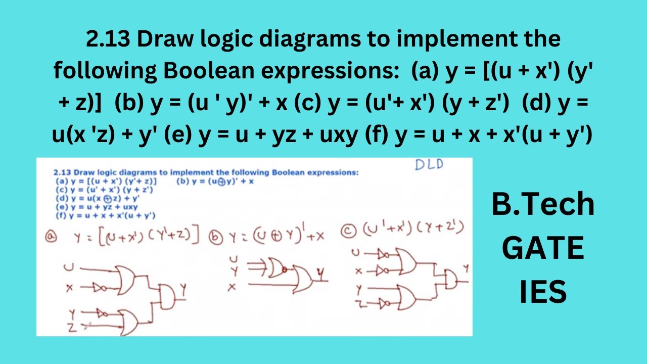
2.13 draw logic diagram to implement the following boolean expressions[diagram] 2 s complement logic diagram .
.

![[Solved]: Problem 1: Question Consider the two circuit dia](https://i2.wp.com/media.cheggcdn.com/media/b71/b715f4cf-dd24-4d3b-83a8-58563c5645ed/phpfrKPCd)


![[DIAGRAM] 2 S Complement Logic Diagram - MYDIAGRAM.ONLINE](https://i2.wp.com/i.stack.imgur.com/caGwn.jpg)